2013년 5월 29일 수요일

C Programming Tutorial - Example 1


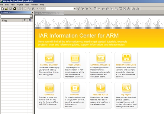
Run "IAR Embedded Workbench for ARM".


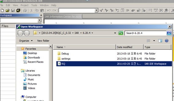
Click “File-Open-Workspace” in menu.


Open “RQ.eww” located in /IAR/6.20.4 folder.


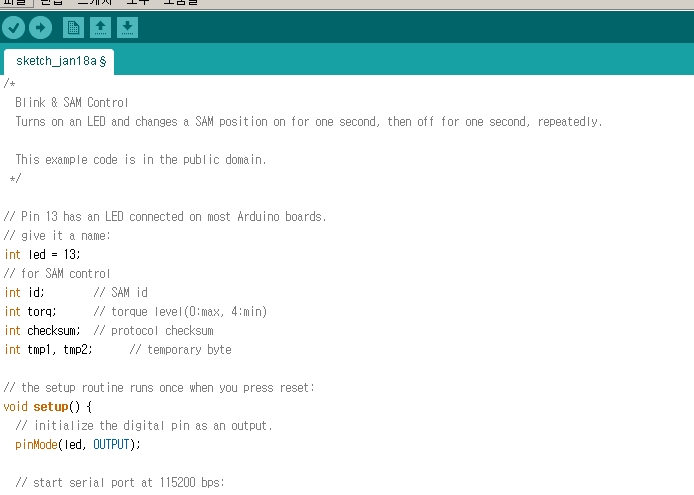
You can see the below C source template.


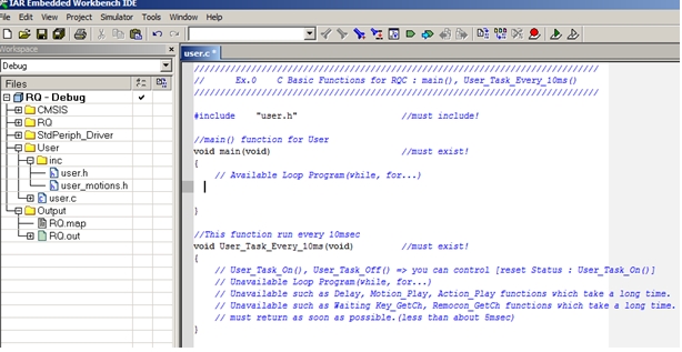
Input C source in “void main(void) function”.


NOTE)
- puts() 
     => Send “string” to COM port of PC.
           Put double quotation mark(“ “) for string.
           null character (‘\0’) is included in last part of string automatically.
- putch()
     => Send “character” to COM port of PC.
           Put single quotation mark (‘ ‘) for character.
- void User_Task_Every_10ms(void)
     => It is called by every 10msec (1/100 sec), such as timer function.
           It is normally used for regular operation.
-ASCII code
   => \r : Carriage Return  (for current line)

   => \n : Line Feed (next line)


Example #1


#include "user.h
void main(void)
{
  puts("\r\n\nHello, RQ World!\r\n"); //Output String to PC
  putch('R'); //Output a Character to PC
  putch('Q');
}
void User_Task_Every_10ms(void)
{

}


Compile it by click “Project-Make” in menu, or press F7.


You can see the compile status and result in the below.

 (errors : 0,  warnings : 0)


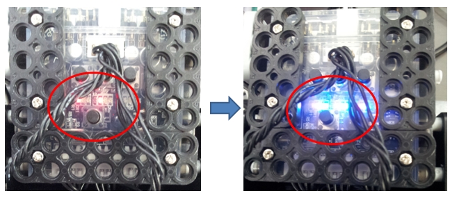
Below is connections for each part.

 (PC ó USB cable ó smart controller ó Li-Poly battery)


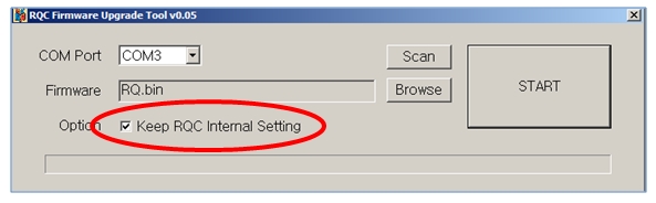
Run “RQC Firmware Upgrade Tool”.


Click “Browse” button to load Firmware file (RQ.bin)


RQ.bin file is selected. Check “Keep RQC Internal Setting”.
This maintains basic configuration of RQ smart controller.

,such as (Zero position setting, IR remote controller…)


“ERROR” message is shown as below
  if RQ smart controller is NOT ready for upload firmware.


Firmware is downloaded to RQ smart controller.


Run “Hyper Terminal” software.

Put any name in Name section.


Hyper Terminal available COM port number is shown as Device Manager Ports section is indicated.
In this example, “COM 3” is used for this project.


HyperTerminal COM port configuration
  (115200 bps, 8bits, None, 1, None)


You can see “Connected” section in the below section.


Press “P” button of RQ smart controller,
then, it shows strings in Hyper Terminal through COM port.


2013년 2월 8일 금요일

MSRDS Tutorial - Day #4


* Play Motion and Music file by using RoboBuilder Brick service


1. Play Motion file

- Add one Data activity.

   We will designate "Motion file" path, therefore, choose "string" option 
   in Data activity.


- Input Motion file path (that you want to play) in your PC directory.
  For file path, use "/" for directory character. 


-  Copy "RoboBuilder Brick" and paste it, then connect with Data activity. 


 Select "PlayMotion" when you see the Connections window.


- Then, you also see "Data Connections" window.

  Select "value" in MotionFile section. 


- Run project, or press "F5" button in keyboard.

- Robot plays "TadpoleSong" motion.


* NOTE) "TadpoleSong.rbm" file should be located
                 in "D://Temp/" directory.


2013년 2월 7일 목요일

MSRDS Tutorial - Day #3


* Microsoft Robotics Developer Studio 4 is installed on Windows 7 or above OS version.


There are two ways to connect between RQ-HUNO and PC.

- Serial COM port : please check your PC "System Manager" COM port.

- Serial Baud Rate : 115200 bps


In current MSRDS 4, you can just set COM port number only, For Baud rate and other configuration is no needed.


1) Run "Visual Programming Language 4" program in MSRDS 4.


- Drag "RoboBuilder Brick" onto Diagram, or you can double click the Brick in order to add on Diagram.


"RoboBuilder Brick" service provide the many functions as below.

 - Connect : To connect with Robot

 - ExecConfigCommand : For internal communication purpose

 - ExecMotionCommand : For internal communication purpose

 - ExecSensorCommand : For internal communication purpose

 - ExecSmartActuatorModule : For internal communication purpose

 - Pause : Pause when "Music" and "Motion" is played.

 - PCControlMode : Enter into PC connection control mode

 - PlayMotion : Play motion

 - RBCControlMode : Enter into RBC (RQC) connection control mode

 - Replay : Re-start from Pause point

 - SetMotionFile : Designate motion file

 - SetMusicFile : Designatte music file

 - SetPlayer : Configure motion play environment

 - SetPlayMotionMode : Set motion mode

 - Stop : stop motion play


2) Connect Robot hardware through Brick service

 - In order to connect with Robot hardware, "Connect" command needs 
   serial COM port number.


 - Add "Data" activity to input serial COM port number.


- Check serial COM port number in System Manager section, then input your 
  COM port number in Data activity and connect to RoboBuilder Brick as below.


If you see the "Connections" window, select "Connect" in To: section.


Then, select "value" in Value section.


Now your Robot is connected with PC through COM 9, if you click "RUN" icon or

press F5  button in keyboard.


All LED of RQ-HUNO controller "RQC" panel LED turn ON, if it is connected normally.


2013년 1월 23일 수요일

MSRDS Tutorial - Day #2


If you click below website,

http://helloappskr.azurewebsites.net/Download/


You will see below webpage.


Download the above programs from STEP 1 to STEP 3 in order.
 
Then, you will find below services" if you search "robobuilder" keyword in "Services" section
after you run "Micorsoft Visual Program Language 4".


In MSRDS4,

  For sensor part, you can use "sound / touch / IR" sensor" of RQ-HUNO.

  "AccelerationSensorModule" service can be used in 5720T-A03 model.

  For "SmartActuatorConfig" service, you can control in each RQ-HUNO servo module
    position separately.


1) RoboBuilder Brick

   => Connect to actual hardware robot device.
   => Play Music and Motion file

2) RoboBuilder SmartActuatorModule

  => Read / Control position value of each actuator of SAM or RQ-HUNO.

3) RoboBuilder SmartActuatorConfig

  => Set up  baudrate, speed, PID gain value of each actuator.

4) RoboBuilder MotionPlayModule

  => Play pre-Programmed in Robot

5) RoboBuilder TouchIrSensorModule

  => Read and config "Touch and IR sensor" value

6) RoboBuilder SoundSensorModule

  => Read and config "Sound sensor" value.


Each Brick connects between function service and robot hardware.

Relationship between "Brick service" and "Other service" is as follows.


2013년 1월 18일 금요일

Android App MotionBuilder fuction


Just released new version (v1.17) of Android App. today!


You can download RoboBuilder Android App. from Google PlayStore

Search keyword is "rq robot" in Play Store.

Updated function is mainly "MotionBuider" in App.


Now you can really do the Motion programming in your Smart Phone, No needs PC.


1) Power On "RQ-HUNO".


2) Run "RoboBuilder Tool" app in your phone.


3) Press "menu" in your phone and connect "RQ-HUNO" by Bluetooth.


4) You can touch "Scan" and find your "RQ-BT" as below and "Accept" it.


5) Then, you can see "Connect to "RQ-BT (5ff00f)"".
    Your RQ-BT unique code (5ff00f) is different. 


6) Touch "Motion Builder", and you will see the Motion Builder.

    Press "menu" and touch "New". 


7) Input any your prefer Motion File Name. (for example. "abc".)
   Then you see the "Motion Config" window.
   Robot Platform is selected as "RQ-HUNO" automatically. 


   Now you can touch "New" for creating "Scene" for RQ-HUNO.


8) Touch ID section "10". and you can scroll the "ID 10"  to the right.

   As you scroll to the right, RQ-HUNO "ID10" servo module moves as below.


9) Touch ID section "11". and you can scroll the "ID 11"  to the right.

   As you scroll to the right, RQ-HUNO "ID11" servo module moves as below.


10) Touch "Confirm" and now "Scene 0" is added.


11) Now, we add "Basic Posture" in Scene 1.
     Touch "New" and then, touch "Dest." a bit longer than usual.

     You will see the ID10 and ID11 value has been changed for Basic Posture.


12) Now, we can test the motion that we just made.

 Touch "Scene 0" section a bit longer, then you can see the various menu.

 Select "Block Begin". 

 Touch "Scene 1" section a bit longer, then select "Block End".


 Try to touch "Motion Test". then you can see the result.


13)  Let's download my Motion to RQ-HUNO. 
       Touch "Download Tool".


14) Touch "Add", and choose Motion "abc.rbm". 

 Then, touch "Transfer File" to download your RQ-HUNO.


After you can see "Complete" message.

Now you can run your motion (Button 1) in "Robot Control" section.


Tip 1)

Try to add more "Scenes" and adjust "Frame" and "Playtime" 
to make more realistic RQ-HUNO motions.


Tip 2)

You can do "Catch-and-Play" function.

Example
If you want to catch "ID 10 value",
then touch "ID 10 Dest. Value" a bit longer time.
Then value will be shown in Blue.


Now, try to move your "ID 10 servo" of RQ-HUNO 

              after "ID 10 Dest. Value" is changed  into Blue.


You will see that "ID 10 Dest. Value" is changed in real-time.


RQ-HUNO with ARDUINO - Day #1


RQ-HUNO is mainly consist of 16 pcs of  SAM-3 robot module.

SAM is stand for "Smart Actuator Module",  and  3 means 3kg.cm torque power.


Let's see how to control SAM-3 with Arduino Board today!


Prepare below.

- ARDUINO UNO R3 Board   1 pcs


- USB Cable                             1 pcs


- SAM-3                                   1 pcs


- 4 pin Cable                             1 pcs


and your PC + Arduino software environment.


For the detailed Arduino software configuration, visit to http://www.arduino.cc/.


For the example source of the SAM-3 control,


Full source is as below.

/*
Blink & SAM Control
Turns on an LED and changes a SAM position on for one second, then off for one second, repeatedly.

This example code is in the public domain.
*/

// Pin 13 has an LED connected on most Arduino boards.
// give it a name:
int led = 13;
// for SAM control
int id; // SAM id
int torq; // torque level(0:max, 4:min)
int checksum; // protocol checksum
int tmp1, tmp2; // temporary byte
// the setup routine runs once when you press reset:
void setup() {
// initialize the digital pin as an output.
pinMode(led, OUTPUT);
// start serial port at 115200 bps:
Serial.begin(115200);
while (!Serial) {
; // wait for serial port to connect. Needed for Leonardo only
}
id = 0;
torq = 2;
}
// the loop routine runs over and over again forever:
void loop() {
digitalWrite(led, HIGH); // turn the LED on (HIGH is the voltage level)
tmp1 = (torq << 5) | id;
tmp2 = 20; // position1
checksum = (tmp1 ^ tmp2) & 0x7f;
Serial.write(0xff);
Serial.write(tmp1);
Serial.write(tmp2);
Serial.write(checksum);
delay(1000); // wait for a second
digitalWrite(led, LOW); // turn the LED off by making the voltage LOW
tmp1 = (torq << 5) | id;
tmp2 = 120; // position2
checksum = (tmp1 ^ tmp2) & 0x7f;
Serial.write(0xff);
Serial.write(tmp1);
Serial.write(tmp2);
Serial.write(checksum);
delay(1000); // wait for a second
}


Then, you need to connect "hardware part" properly.

Hardware Connection


For the detailed hardware part connection,

Make the cable as shown in the right.


SAM-3 pin layout is as below.
 
For the Rx/Tx connection,
 
    -  connect Rx of SAM-3  with Tx of Arduino board.
    -  connect Tx of SAM-3  with Rx of Arduino board.


After proper connection of all hardware part, then connect USB to PC.

And Compile the source and Upload to Arduino board.


Then, you will see SAM-3 moves from 20 degree to 120 degree continuously